How to create a simple circuit layout inside AutoCAD
Essential Steps for Drawing Electrical Circuits
- Selecting the Right Symbols: Choose between Imperial or Metric symbols from the Electrical Symbol Library.
- Setting Up Your Drawing Sheet: Decide on your scale and insert the appropriate drawing sheet.
- Adjusting Drawing Settings: Check and modify settings like Ortho mode and Snap for optimal design accuracy.
- Drawing the Circuit Layout: Start with essential components and progress to more complex elements.
- Adding Components and Pushbuttons: Insert relays, pushbuttons, and other elements into your layout.
- Creating Interconnections: Draw lines to connect the components, ensuring the flow of the circuit.
How to Create a Simple Circuit Layout In AutoCAD
After installing the Electrical Symbol Library – start AutoCAD. On the Menubar, you will find headings for the libraries you have installed. This library provides a powerful method to draw circuits and electrical layouts in AutoCAD.
Play the 3-minute video below now!
The exercise demonstrates the ease of creating a simple electrical circuit layout using our Electrical Symbols for ANSI Y32.2 & IEC 617. It’s a perfect starting point for those wanting to learn how to draw circuits using AutoCAD.
Choose Imperial or Metric Symbols for your Circuit Design
The electrical symbols in AutoCAD come in two main versions – Imperial and Standard. In the software menu, these are indicated as “Y32.2 (Imp)” for the Imperial version and “Y32.2 (Met)” for the Metric version. As illustrated in our video, we utilize the ANSI Y32.2 Symbol Library to demonstrate how to draw circuits quickly and accurately.
Opt for the (Imp) version when working on standard-sized drawing sheets, whereas the (Met) version is more suited for metric-sized sheets.
Incorrect library selection can lead to sizing issues, such as tiny electrical symbols if Imperial symbols are used on Metric sheets, and vice versa, oversized symbols on Imperial sheets.
Deciding Scale and Inserting Drawing Sheet
After choosing the correct symbol library for your circuit drawing, there are two approaches you can take. The first is to import or develop your drawing sheet. To do this, right-click on the appropriate Menubar heading and then on “Parameters” from the dropdown menu. This action sets the correct Snap value and other parameters for your circuit design.
Alternatively, you can select the required drawing sheet size from the bottom of the dropdown menu and hit ‘Enter’. This action displays the sheet with pre-set correct parameters, streamlining your process to draw circuits.
Checking and Adjusting Drawing Settings
For most schematic diagrams, you will have connecting lines running either vertically or horizontally, and it’s important to enable “Ortho mode.” This mode can be toggled “On” or “Off” by pressing the “F8” key. Additionally, ensure that the Snap settings are correctly set to either a 1/4″ or 1/2″, which aids in aligning the electrical schematic effectively. Also, verify that the OSNAP settings in AutoCAD are activated.
Drawing the Electrical Circuitry
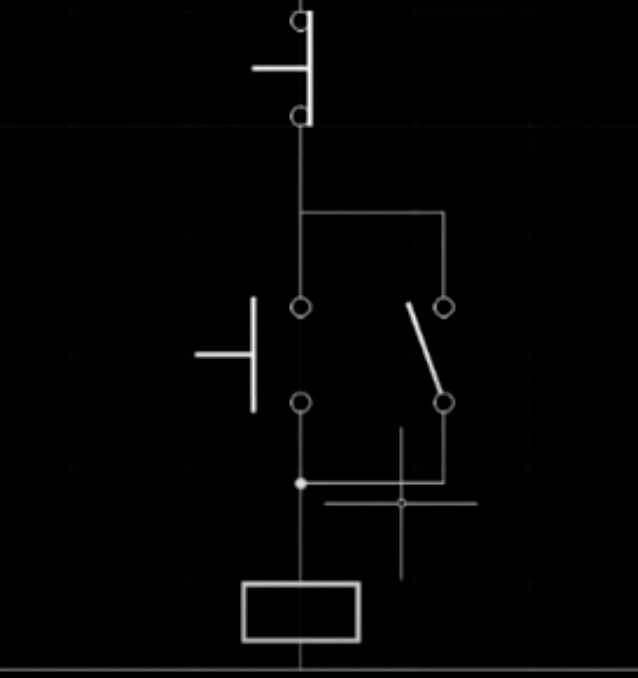
Let’s try designing a simple Electric Motor Stop/Start circuit—Access ‘Relays’ from the dropdown menu to start drawing the circuit. An Image Menu with a descriptive box at the side will appear. Choose the relay coil of your choice by double-clicking on it. The symbol then attaches to the mouse pointer for easy placement on your drawing sheet.
Drag the symbol toward the bottom center of the drawing sheet and double-left-click to transfer the symbol from the mouse pointer to the drawing.
You may notice that the first click of the double click fixes the symbol to the drawing and prompts you for the symbol to be rotated. If the Ortho mode is on (F8), the symbol can be rotated in 90-degree increments. Having rotated the symbol to its desired orientation, left click a second time and the symbol is now anchored into the drawing.
Adding Pushbuttons and Interconnections
Open the relay image menu again, and select a normally open contact. Drag it into the drawing area and position and rotate it about 1 inch or so above and 1/2 an inch to the right of the relay coil.
From the drop-down menu, click on Switches/Pushbuttons, then Operators/PB’s. From the image menu, select the normally open push button and position it directly above the relay coil and level with the normally open contact. Rotate it before the second click.
Go back to the menu and this time select a normally closed pushbutton and position and rotate it about 1/2 an inch above the normally open pushbutton.
Finally, choose ‘Continuous’ from ‘Choose Linetypes for the interconnections.’ Use ‘OSnap’ and ‘Insertion’ under Object Snap Tracking for precise line ends. Complete the interconnections by drawing two horizontal lines representing the Live and Neutral feeds.
We hope this tutorial has shown you the advantages of using the Electrical Symbols for ANSI Y32.2 & IEC 617 library.
Get started now with this Electrical Symbol Library today.
We’ll send you detailed instructions on how to get it installed, plus you can call us for help if you have questions.
This comprehensive guide is designed to assist you in creating simple yet effective electrical circuit layouts using our Electrical Symbols for ANSI Y32.2 & IEC 617. Enjoy the process of learning to draw circuits using this tool!